
I was able to pick up a Lambda-class shuttle for FFG's X-Wing game over the holidays for about 1/3 the retail price. When I got the package, the mini itself looking amazing while in the box but, upon opening, I found out what so many of you already have - the wings don't fold down correctly. After reviewing the official FFG forums and hearing how FFG claims that the wings as provided are in the correct position, I'd first like to show how this is a load of bantha fodder. Observe:

Let's go to the videotape!
Shuttle Tydirium (RoJ film footage, 1983)

ILM Promo image (RoJ, 1983)
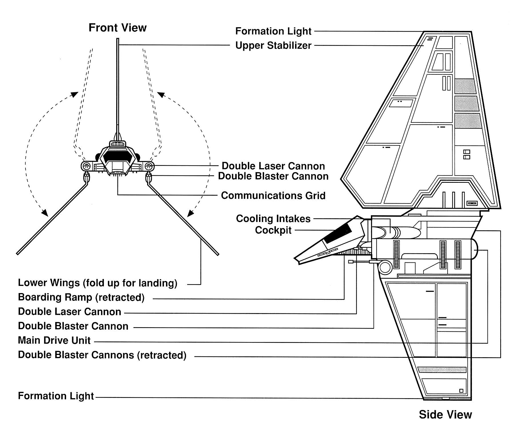
Lambda-class shuttle schematics (SW Technical Journal, 1994)
Lambda-class Shuttle card (Decipher Star Wars CCG "Endor", 1999)

Col. Jendon card art (FFG X-Wing, 2013)

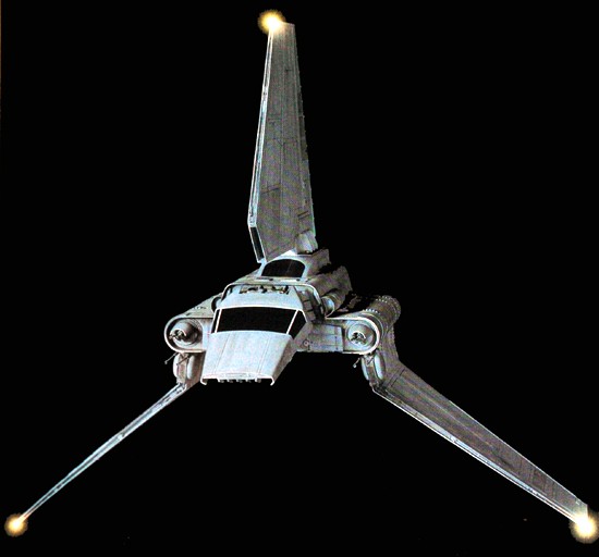
The above images show that a near-90 degree orientation for the deployed wings is correct, and that (due to either poor design or bad manufacturing) the FFG miniature's stock wing orientation is incorrect. The pic below shows the correct angle after using the popular "pinch" method...which leaves a gaping 1mm wide gap in the fuselage sides.


In an effort to help others get it right, I volunteered my cheap Lambda miniature for experimentation. Had I paid full price, I probably wouldn't have gone in so blind (not to mention being rather angry at paying $30 for an incorrect miniature). So...let's fix it! You'll need the following:
- An X-acto knife (preferably NOT the regular, light duty #11 model)
- A thin, strong metal tool (preferably one you don't mind breaking)
- Jeweler's files
- Super glue
- PATIENCE
I won't lie - this tutorial could potentially break the miniature. BUT, the plastic that molded the Lambda out of must have some sort of adamantium in it, because the only thing that broke during this entire tutorial was both my heavy duty X-acto blade and a metal file. Practice shop safety - wear eye protection and work in an area where broken X-acto blades won't be a safety issue.
Most importantly - Be Patient! This can be a time-consuming project that can get easily frustrating. Work slowly and take a break.
First, pull off the dorsal (top) fin by pulling it away from the body with steady, constant pressure. You should hear a sharp crack when the super glue holding it in breaks up.

Next, work your blade between the upper fuselage and the forward bulkhead, just over the bulkhead blaster cannons. Once about halfway inserted, start leveraging and wiggling the blade up and down. Do this to the other side as well.

Eventually, you should be able to work the pieces apart far enough that you can insert your larger metal tool. Continue leveraging the pieces apart with your tool. Be careful to avoid damaging the thin plastic of the upper fuselage overhang.

You may see the bulkhead tab that holds the cockpit tab secure inside the body. If you do, you've probably broken it away from the cockpit tab. Now you can remove the cockpit like you did with the dorsal fin - pull straight away from the body by applied steady, constant pressure. You may need to run your X-acto blade around the cockpit "neck" where it joins the forward bulkhead to break up the super glue there. The cockpit should come off, though you may break the internal cockpit tab. THIS IS OK (the internal tab is unnecessary when re-assembling the mini).

If you hear a hollow breaking pop when leveraging the forward bulkhead, congratulations - you just broke up one of the internal assembly points. Do this to the other side until you hear the same. The front half of the body should be noticeably easier to bend apart. STOP, turn the mini over....
And run your blade along the seam underneath the engines. Insert your blade into the seam and leverage under each engine separately (this is where the rear internal assembly points are).

After "popping" each rear assembly point, the body should now easily come apart. Cut down as much of the internal assembly points as you can.


The pic below shows the little tab that's caused all the problems. It's located just above the wing blaster cannons on the first strut. You'll notice that this tab is alinged parallel to the lower wing and prevents the wing from going to their correct orientation because it hits the internal tab inside the body. Remove this tab.

Clean up the paint, black wash, and mold lines inside the wing assembly and file down the inside of the wings closest to the body.

Clean up an excess super glue around the cockpit neck and dorsal wings. You may want to use this opportunity to remove any of the mold lines on the mini as well. When you're done, bend any pieces back into shape if they were deformed during deconstruction. Carefully seat the wings into their places and apply a THIN bead of super glue around the lower fuselage half. DON'T GET ANY ON THE WINGS!!! Join the fuselage halves together and hold until the glue is cured.

See? No gap anymore...

Apply super glue to the cockpit neck and re-attach. Apply super glue to the dorsal fin and re-attach. Congratulations on your corrected shuttle!


5 comments:
Wow, it's more in-depth than I'd anticipated. Thanks for sharing the pictures!
This must have been resolved in manufacturing, I recently purchased a Lambda Shuttle and it can fully the wings to proper positions with no problem.
My wings folded correctly, however the dorsal fin was not straight, so thanks for the advice on how to pull it off!
Thank you for the excellent Tutorial! I was a little aggressive and cracked the front bulkhead the cockpit attaches to, working to break off that internal tab is probably the best method.
Post a Comment